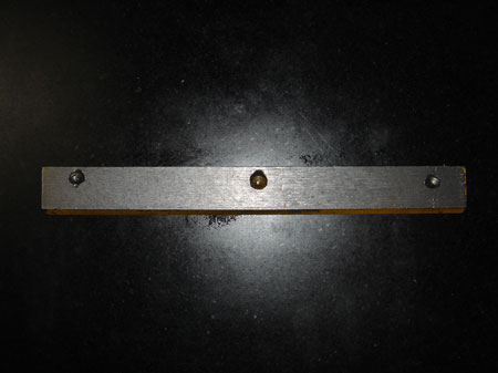
This is the original gib from the X axis. It's easy to see that the countersinks for adjusting screws are not parallel with the edge of the strip. Probably not a good thing. I was having problems with the X axis "sticking" when I tightened down the screws.
Time to make up a new one!
I found a piece of steel in the scrap bin, about the right size, so I decided to go for it. Brass might have been better but I didn't have any on hand.
At this point the hope was to help reduce the problems I've been having with the X axis rotating around the Z when I would switch directions feeding the table. I couldn't get the strip tight enough to take up the play without it locking up or sticking on the ways.
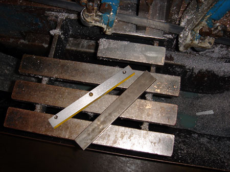
I trued one edge of the steel and then laid out some scribe lines with the surface plate and height gage. These dimensions need only be rough.
I squared up the remaining faces and milled the strip to size.

Next I chamfered each edge with a 60 degree chamfer tool. I set the strip up on a .5" parallels and then used a couple of clamps. I squared it to the table with my LC/EF.
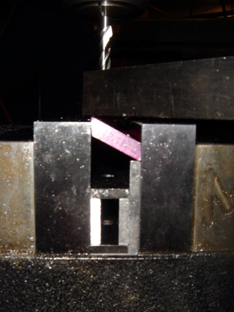
Got parallels? This was getting a bit creative but it worked great. The top of the strip sticks up just enough that I can push down on it with a couple of table clamps. Of course I need countersinks to be on the appropriate angle and this does the trick. I just eyeballed it.
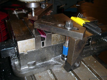
Hey, isn't work holding a gas? I threaded the blue nut onto the T nut and then threaded a short stud into that. I only had to countersink in three places, each end and the middle, which worked out nicely with the big clamps.
Again using the LC/EF to locate my punch marks.
This would be a good time to note, the CS for the locking handle sits a little bit above the counter sinks for the adjusting screws.
To locate the holes I test fitted the strip on my machine. I screwed in the handle and two screws so they would mark the layout dye. Then I used a center punch on what looked like the center of the mark. I punched one end and then just traversed the table over to the other side to ensure these two countersinks were on exactly the same plane.
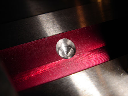
Hey that looks nice! I just used the profile of the drill point to give me a taper in the bottom of the CS so it would be self aligning. Then I had to spot face to allow clearance with the adjusting screws since the would be coming in at an angle.
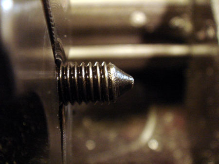
This is the tip of the adjusting screw, the locking handle had a similar profile. I thought I could do better.
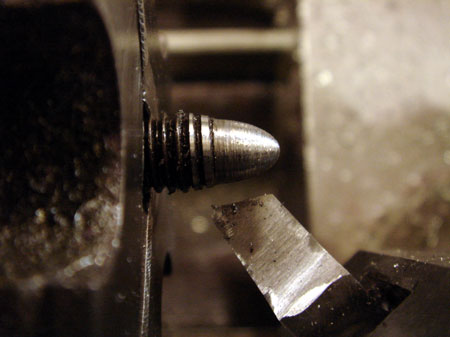
I just turned the end by eye using the X and Y feed at the same time. Then I set the tool at an angle to blend into the threads to help clear the seat on the gib strip.
I felt the round nose would self center much more effectively.
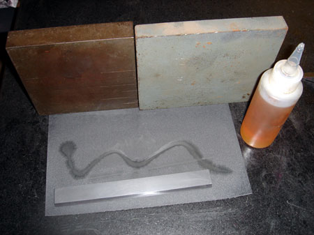
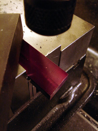
I lapped the sliding surface with wet sand paper on the surface plate, down to 600 grit. The big angle plates help keep the paper from moving around so I can use two hands. It took forever to get all the tool marks out. My kingdom for a surface grinder.

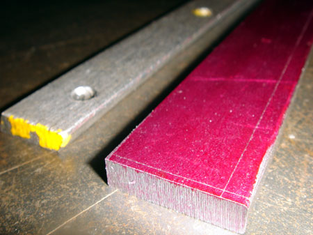
So this is the old strip and the new strip. On the new one, you can see that the CS for the locking handle rides a bit higher. Does it on the old one? Who knows.
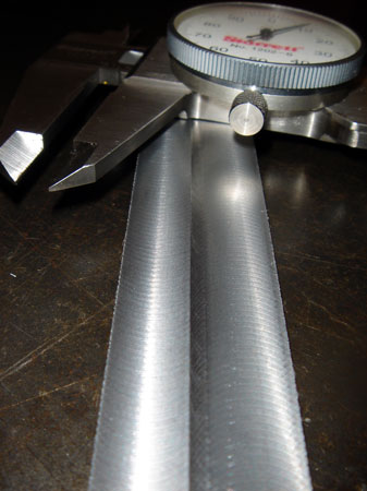
The big question: was this an improvement? Let's measure!
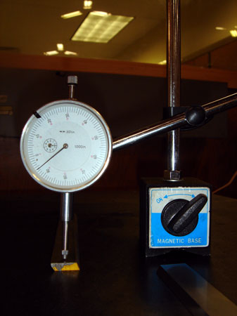
The old strip is about .006 out from end to end.
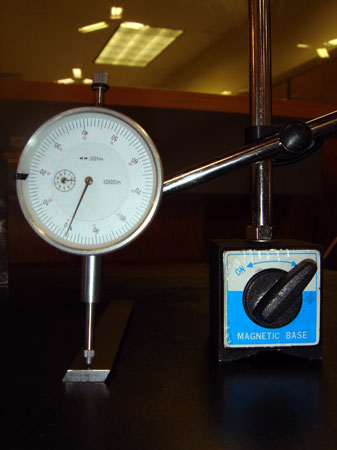
My new gib is out by just over .001 for six inches in length. Well, that's about six times better. Not perfect but I'll take it!
Well, how does it function? It fit the machine quite nicely. I've adjusted the gib and get a much more consistent slide along the X axis with much less friction than before. I've got the rock in the table down to about .0015. With the old gib I could do no better than .0025 and that resulted in significant friction and sticking.
Not perfect, but I measured an old clausing lathe that seems quite capable and it showed just under .001 deflection when reversing travel. I'd call that pretty good for the shoptask and I don't know what I could do to make it better.