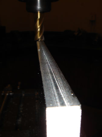
Just thought this was a cool photo. You have to love the finish a power feed can provide.
Right now I'm also working on a power feed for my X axis that will mount where the CNC motor should mount. I'll try and drive the leadscrew with a timing belt to the gear that is provided for the CNC conversion. I'll power it with a DC controller from KB Electronics via my new switch box.
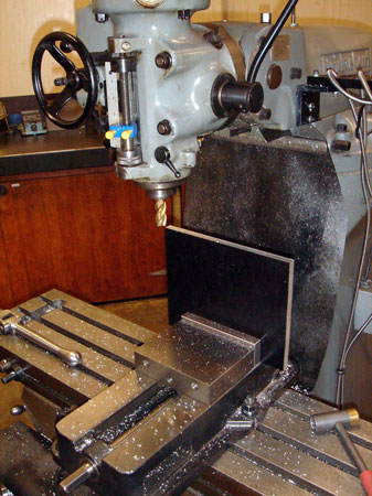
This is work that would be really hard on the shoptask. Just getting this plate squared up.
I'm going to mount the motor with the foot parallel to the chip tray instead of on that angled bracket. I got myself some Fenner link belts so I can adjust the belt length for tension instead of moving the motor.
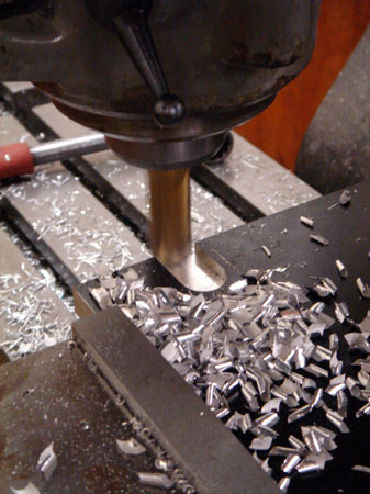
Here I'm cutting a notch in the corner so I can fit this to the original mounting location...this will become more clear.
I pretty much eyeballed this up to my scribe lines. Not much in critical tolerance required here. That's a 3/4" mill and I cut it out in two passes.
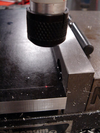
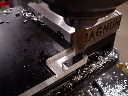
Now I had to make four holes for the mounting bolts. I scribed some lines in the corner where I would zero my DRO and drill the first hole. I used the laser to indicate the intersection and then just used the dimensions from the manufacturer's technical drawings to make the rest of the holes.
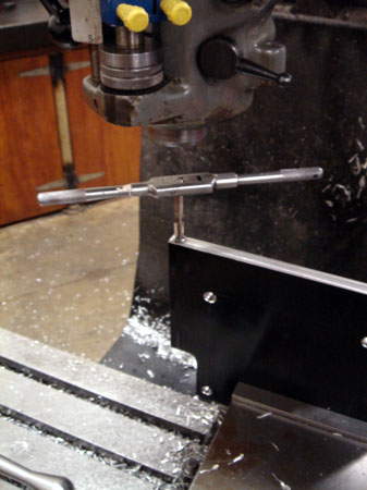
I drilled and tapped this end 5/16 UNC.
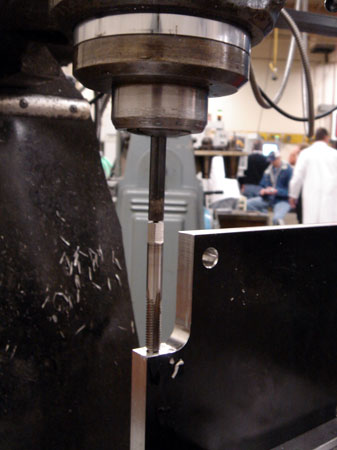
Hmmm. Looks like my tap isn't long enough to let me hold it in a chuck to get it started. I used a transfer punch in the collet to engage the little hole in the back of the tap to hold it straight. Then it was just a matter of turning the tap with a crescent wrench. I'll remember to consider my tap length in the future.
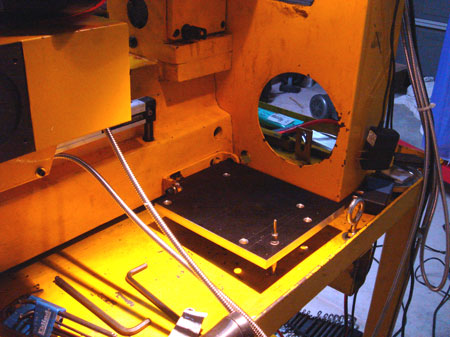
Here you can see the setup. Right now I just have the plate snugged with the bolts in back so the plate is basically floating, but level so I can punch two holes through the chip tray.
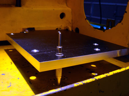
Just a better view, the center punch fit the 3/8 hole perfectly.
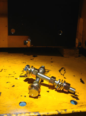
This stack of hardware is going to secure the motor mount through the holes I just made in the chip tray.
You can also get a better view of the rear part of the mount. I had a little more play than I wanted...my cardboard model wasn't exactly precision, so I had to put a thin nylon washer in to take up the slack.
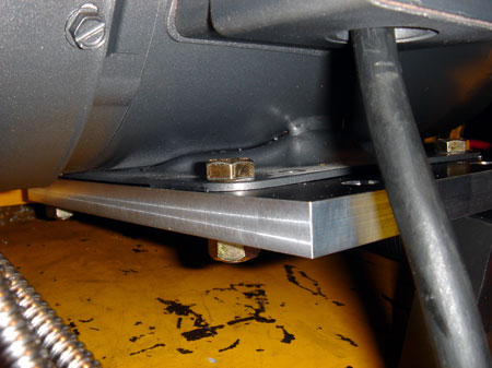
I used a through hole and a nut on the back instead of tapping the plate. Tapping might have been cleaner but I wanted to make sure the mounting holes wouldn't be off so much I couldn't get them in. Turns out I could have tapped them.
Not exactly sophisticated but it works well and gives me a slight bit of adjustment up and down to make sure everything is horizontal. My chip pan isn't exactly flat.
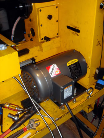
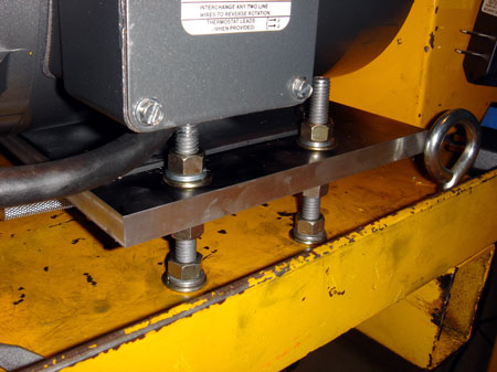
Well, there it is. I've got about 1/4" clearance between the front of the motor and the enclosure. Fortunately I measured right. It seems rock solid to me. Gonna have to fire this thing up soon.
The motor is a bit off center because I had to leave enough room for the DRO scale to clear. These motors are substantially larger than the original ones. I opted for the direct drive to the spindle and cleaned out all that other junk. That's pretty slick.
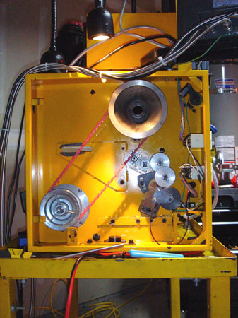
I also found that Dychem remover works fabulously for cleaning out the black much left by the original belts. Speaking of belts. Whoever came up with these link belts is a genius. They should pat themselves on the back.
Anyway, the way I have it set up, the motor pulley is slightly smaller than the one on the spindle. I'd guesstimate I'll get about 1500 RPM top speed and don't plan on needing much more than that. Things start flyng all over the place. I might even gear lower in the future. The Fenner belts are so great because I can just change the pully orientation at will and just add or take out links to get the right length.