My refurbished motor is face mount only. Obviously this was going to be a bit more of a challenge than making the mounting bracket for the lathe.
Again I used some 1/2" anodized aluminum plate and squared up a couple of pieces on the Bridgeport.
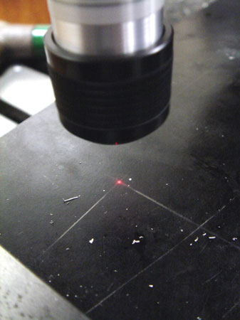
The layout is with pencil and an adjustable square. One mark was enough since I used the DRO to determine the other three locations.
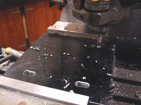
This plate will bolt up to the existing bolt holes, but with upgraded hardware of course. I wasn't 100% on the dimensions so I cut some slots in case I needed some fine adjustment of the motor height.
I plunged two holes with a 3/8" two flute mill for each slot. I left them .010" from the end of the desired slot length and cut down the remaining material in three passes with the .010 to clean up at each end.

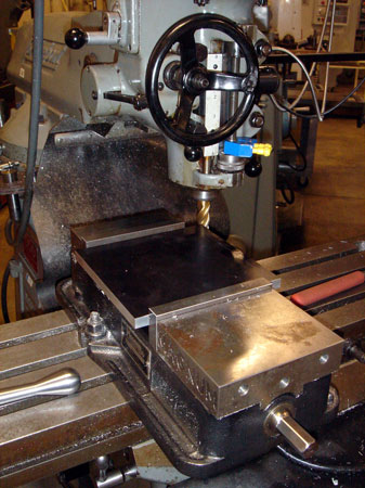
I suppose now is a good time to point out my dodgy work holding. I'm very near the capacity of the vise with a 7.5" width. This is the setup for drilling and counter boring all of the 17 holes for some 1/4-20 SHCS.
Since I'd be working so close to the jaws I couldn't use 1/8" parallels. I found these honkin' ones instead. At this height the jaws don't have much to hang on to. I drilled carefully.
This project was the biggest test of the LC/EF that I have personally undertaken. Not an engine, but there will be plenty of opportunities for misalignment to sneak in. I used it for six different setups.
Did I mention I was drilling close to the edge?
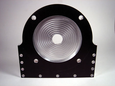
Ahhhh the magic of CNC. Sorry for no video, my bad. Actually, only the pocket, the four larger mounting holes and of course the radius was done on the HAAS. The motor has a flange on the face that will fit inside the pocket. The fit is within about .003-.004 (based on feel) after I measured the flange with a 6" mic and programmed the pocket to .002 oversize. Very close to no slop.
I drilled and counter bored the other 12 holes on the Bridgeport, using the DRO after indicating one corner moving .25 in X and Y to locate the first hole (1/2" plate).
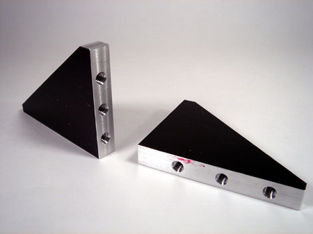
The gussets stared out as a single square piece. I drilled and tapped all four edges before cutting them apart (corner to corner) on the band saw. I went back to the Bridgeport to clean up the surfaces that hadn't been drilled and tapped. I did both parts at once to try and make them as identical as possible.
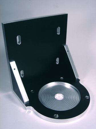
Assembed of course. Everything seems to be remarkably parallel and perpendicular; no gaps, edges meet nicely, no binding on any of the screws. That one surprised me the most. I figured with 17 I was bound to screw something up.
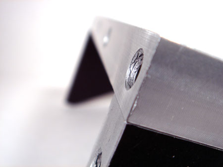
I removed the pocketed part of the plate and left the gussets tight on the other in order to check the fit at the corner here. Running my finger over the seam I couldn't feel any significant discrepancy.
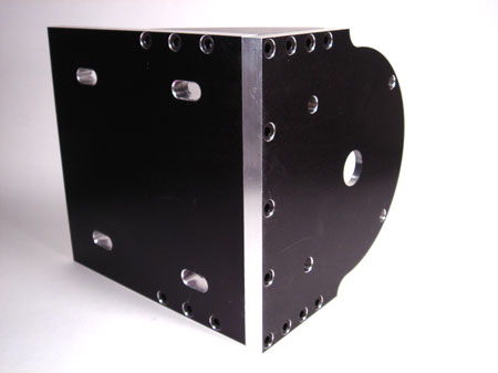
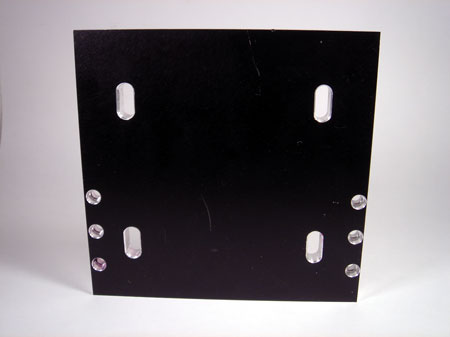
Just a shot of the back side. Too bad once the motor is mounted on here I will never see that cool spiral pocket again...if all goes well.
Time to get this bad boy mounted up! Click here to see my VFD conversion and some shots of the motors in place on the machine.