Well, here goes. I just had to have a ball turner and Steve Bedair's seems to be the weapon of choice. It also worked out to use some 2.5" aluminum stock I had lying around. Yeah I know steel would be best...but you gotta work with what you have.
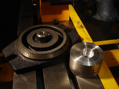
The first step was to take the vise off its swivel base and drill/tap the center post. The main point was that I wouldn't have to find a piece of metal to use for the base...and gee, this just worked so nicely.
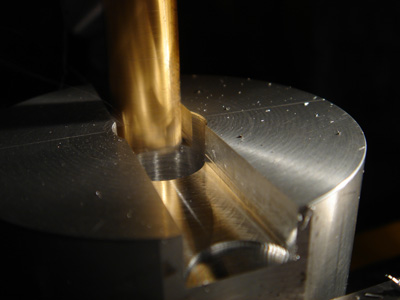
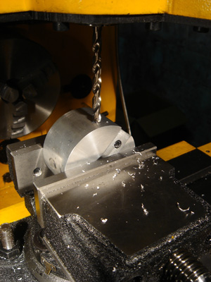
The billet on the right has been drilled for the screw (8mm x35mm), bored to fit the post and bored on the other side to accept the cap screw head.
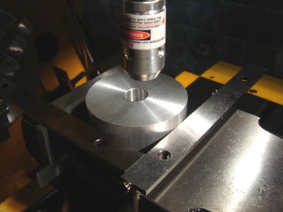
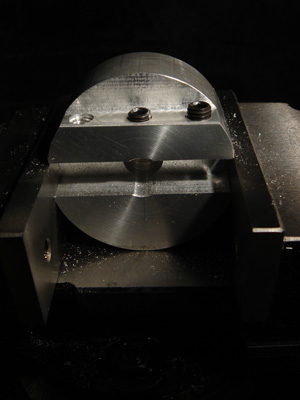
I decided I would need to scribe a couple of 90 degree center lines to help me in the future. I wasn't sure what the best way to find the center of this was...probably good to do it before I drilled it out.
So, I took a couple of parallels and secured them to the vise with magnets. The corner where the parallels meet should give me a good reference point and the LC/EF worked great for this.
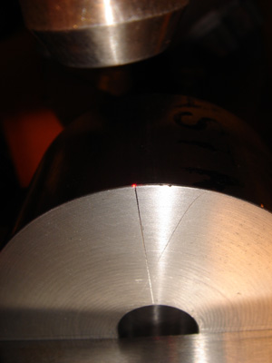
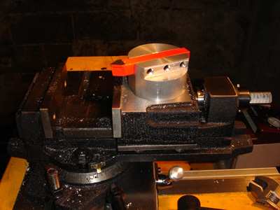
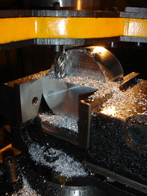
Next I thought I would cut a couple of flats onto the round to use for clamping the work. I'm very close to the max capacity of my vise so V blocks were out of the question...and I don't have any.
Again, the LC/EF made it super easy to find my scribe line.
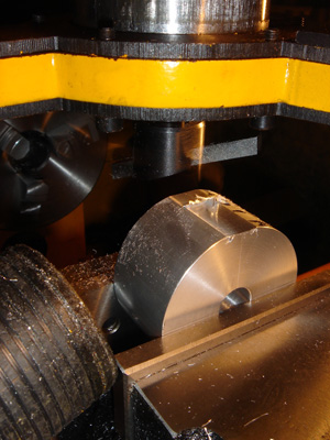
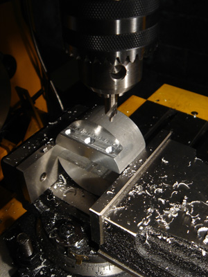
My first use of the fly cutter...and maybe the last. I found a really bad knocking sound showed up because the mill spindle pulley has a sloppy fit on the splines.
Every time the flycutter came around it whacked the splines against the pulley and made a nice hammering sound. I busted out an endmill to do the other side.
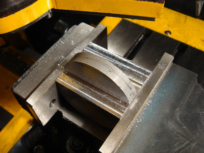
Ahhhh slotting with the 1/2" endmill. Now that is beautiful, no muss no fuss. The flats I cut also keep the work aligned properly when I flip and grip. I went .5 wide and .5 deep...just like Steve.
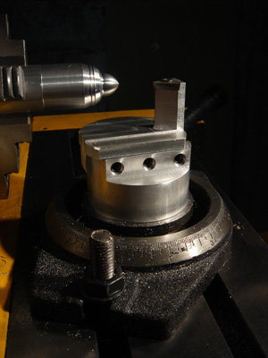
I decided to cut down the side where the screws would mount. It seemed this would be easier to drill and tap. I also went with 8x10mm instead of 6x8mm set screws.
Well, that went nicely and I'm pretty pleased so far.
I took this opportunity to do a quick test fit with a 1/2" tool.
This will eventually be the post that holds my indexable insert.
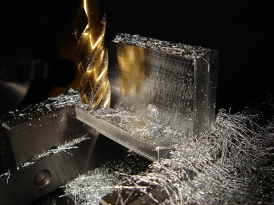
I flatted this piece too, flipped the sucker on its side and went after it with a 3/8" roughing endmill. Man, that thing eats aluminum like a fat kid with a family size bag of doritos.
This orientation didn't turn out to be the best. If I had to do it again I'd flip the work another 90 degrees and do the entire "bottom" in one clamp. With this setup I am doing one "side" and then the other, which makes it harder to get things horizontally symmetrical.
Ka boom, one side down...next!
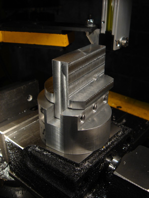
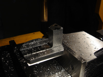
Now I'm finishing of the surfaces with a 1/2" mill. I made the vertical bit (that would hold the carbide bit) a little wider than .5" just for some extra rigidity.
You can see a 1/4" inch hole that I drilled for my reference point on the next step.
I did another test fit just to see how things were going and everything looked very close.
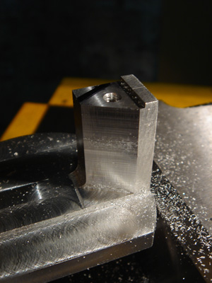
Time to take out the rest of the vertical. Here you can see the hole better. I just cut till I was close with the rougher and then finished up with the 1/2" end mill.
All done and looking good. I set the indexable carbide on the top of the post just to check the dimensions.
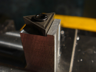
Just a little off the top. Then I drilled and tapped the hole position I calculated (using the LC/EF) so I could figure out how to cut the clearance angles on the side of the post.
Also, since the insert has clearance on the bottom, I had to measure carefully. You can se in the photo there is a gap. This will be filled when the insert is at full depth.
I just snugged the carbide insert down, cut a sharpie to a chisel point and inked along the side of the insert. Then I just machined it down till all the ink was gone. This seemed to work perfectly.
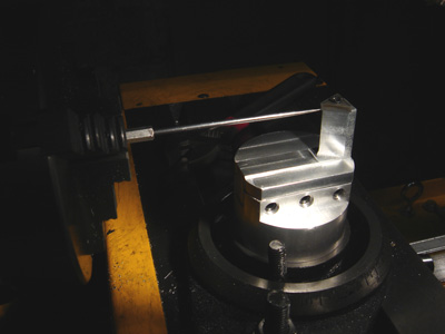
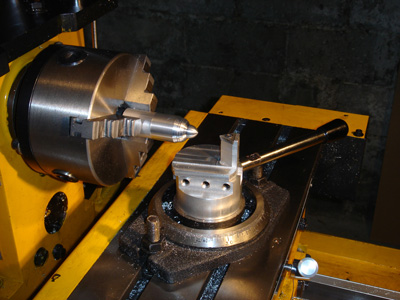
I clamped a little pick in the chuck to test the center height of the post. I deliberately cut it quite high to make sure I would end up with enough material at the end.
I tightened all the screws and just machined the seat for the bit this way, instead of going back to the vise. It also allowed me to shuttle back and forth between cutting and testing the tool height. I just eyeballed it till it was right.
I was feeling done, but remembered I was gong to need a handle to make this thing work. My machine came with the wrong handles, so I had a couple of extra ones lying around.
I just made this 45 degrees from the main axis.
Luckily it occurred to me my T bolts were really high so I mounted the handle quite close to the top of the base. I didn't measure, just crossed my fingers, but it came out just right.
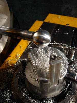
Well, that is that. It works great and seems quite solid despite my jerry rigged solution. You can see I left big flanges instead of going with a straight "L" shape for the post.
It was just easier not to machine everything away. I also figured it would help keep the whole thing more stable...though probably not in reality.
Not really trying to make anything, I just wanted to cut some metal and see what was going on. I guess my next project will be to turn a ball for the end of this handle...stay tuned.
I couldn't really visualize exactly how the tool was going to work, but it also seems that by positioning the tool in a certain way I'll be able to cut a lot more shapes than just a round ball so I'm pretty excited to try and come up with some interesting things. Chess anyone?
Well, here it is. I made a ball for the handle of the ball turner. Makes sense right?