I'd been trying to wrap my head around this one for a while. Finally it occured to me that the bolts on the 3 Jaw chuck are around the perimiter.
Chuck is 5 inches...rotary table is 4 inches...eureka! (Good TV show by the way) This will make more sense in a minute.
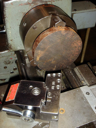
I found this steel round, as is, in the junk bin. Gotta love a junk bin.
Now I'm boring a hole, after facing the other side, so I can grab this thing from the inside. The tool post is at such a funny angle because I'm chamfering that inner rim.
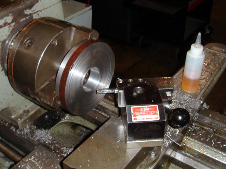
So far I've faced the round, turned the edge parallel and bored out the center. In this photos it's been flipped and gripped. I had to bore enough to get the jaws on the inside so I could significantly turn down the diameter without obstuction.
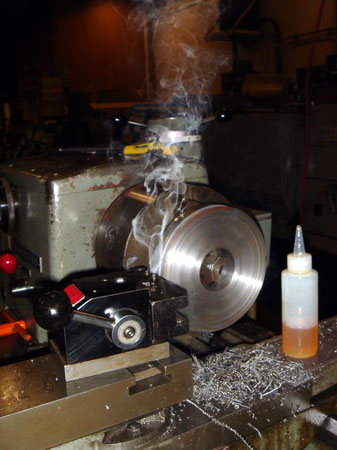
I'm actually using a 5/16 HSS tool that I ground for aluminum. It worked surprisingly well but I was pretty worried about overheating the bit. Even at lower RPM a round that big has got some significant surface feet at the outer diameter. Sooooo I was using some cutting fluid which was smoking A LOT. It was giving me a headache...cool pic though.
Still choking on fumes. I'm turning down the recess where the adaptor will sit on top of the rotary table. I've also taken about an inch and a half off the diameter. A lot of work for a HSS tool you say? Ahhhhhh. Next!

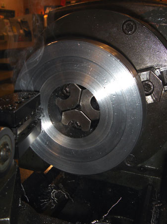
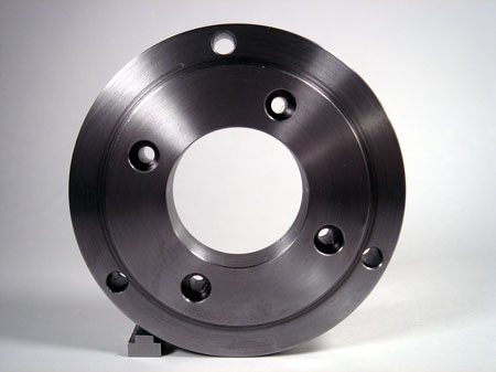
This might be my favorite photo so far. I got out an indexable tool (coated) and turned the rest of the dia. dry and with enough chip load to give me these fantastic blue sixes and nines! Very exciting for the novice machinist.
Also very exciting when blue hot steel chips go down the front of your shirt. I was running pretty fast and those things were flying everywhere.
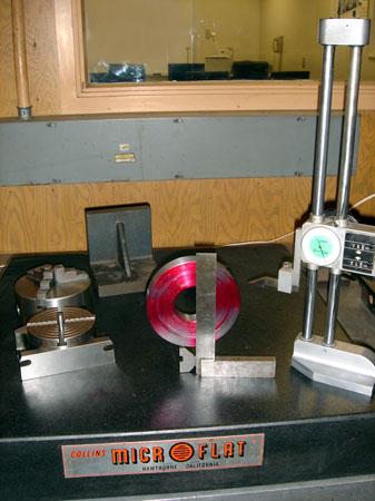
So one side has a recess where the rotary table (left side) seats. Then there is a proud area on the other side to accept the 3 jaw...just like the back plate on the lathe spindle. I used the actual parts to test fit and just went by feel instead of precise measurement.
Time to lay out the three holes to mount the chuck and the four holes for the T slots in the rotary table. The dia. of the bolt circle isn't that critical, just that they are all exactly 90 degrees apart. I made short work of this with a V block, machinists square and the height gage.

I used my trusty laser to line up the scribe lines exactly with the XY axes on the mill. This is really the kind of work the laser excells at (not a cheap plug, just the facts). This way I could take advantage of the DRO and poke holes in this piece of steel like it was my job.
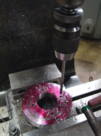
I reamed the four holes...because it leaves a nice finish.
Go back an hit it with and endmill for the quick counter bore.
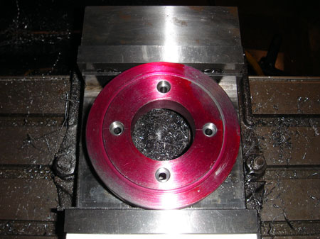
I actually located the three holes for the chuck by using the faceplate that came with the shoptask. It already has holes in it and fits perfectly over the adaptor...soooo...I used a punch and the LC/EF to locate the punch marks. No layout at all. Oh, by the way, it fits.
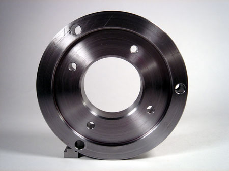
This is a shot of the side that mounts to the rotary table. As you can see the tree holes hang out over the edge perfectly. First I lock it down to the rotary and then plop the chuck on top and I can still acess the three bolts with an allen wrench (or hex wrench if you prefer).
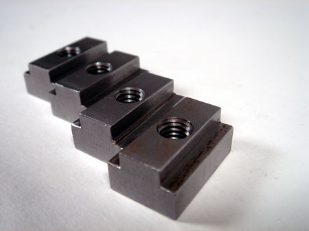
My rotary table came with two t nuts but I went ahead and made 4 new ones. First I squared up a long bar. Then I cut off 4 chunks on the band saw. Since they were all dimensionally similar I gang milled them and drilled tapped all in the same setup.
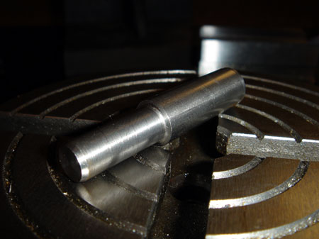
The last thing I needed to make my cheapo rotary table into a usefull device was a way to center it under the mill. I found a little scrap of CRS and made a pin that fits in the center hole. The other end is faced flat so I can center it using my laser. The hole isn't tapered so it was straight forward. It makes a nice little "pop" when removed from the hole.