Have I ever mentioned how much I love Ebay?
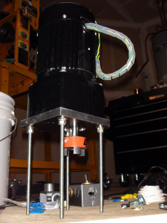
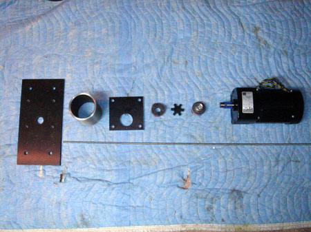
This is a NIB Bodine Electric AC gear motor:
TYPE (42R5BFS1-E3)
115V, 60 HZ, Single Phase, 3.6A
AMB 40`C, INS B6, Time: CONT.,
20-1 RATIO, 85 RPM, Torque = 90" LBS
$150 bucks including shipping. Retial: $385.00
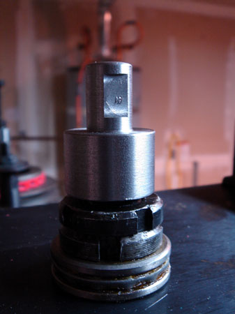
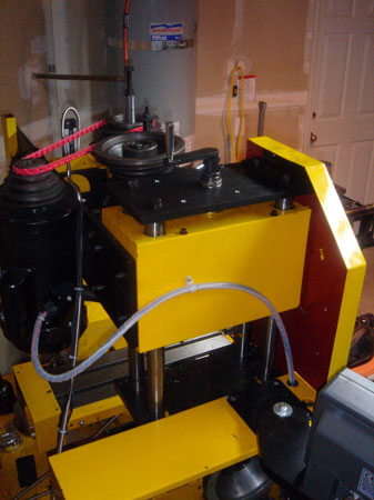
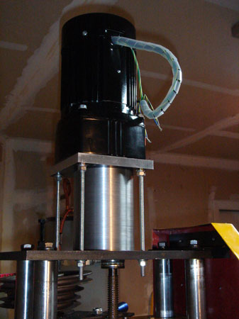
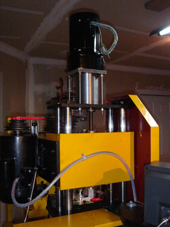
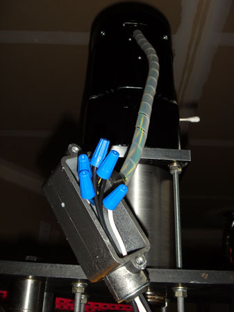
Picutred is my final assembly before being mounted on the machine. I thought this view reminded me of War of the Worlds...but with less fleeing in terror and people getting vaporized.
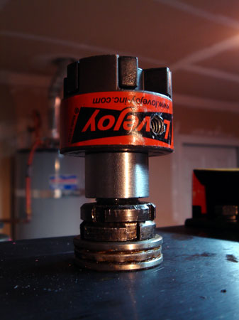
I am getting a bit ahead of myself though, so let's back up. I bought some Lovejoy couplers from MSC but of course the mill column screw has a square shaft. What to do?
Initially my plan was to machine the actual coupler, like Bloy did (www.cnczone.com). MSC listed the coupler material as "plastic" for the 1/2" (L75) size copuler. Turns out it's steel and I wasn't sure how hard. I banged them together and the noise they made said, "I am hard, don't machine me." So...I didn't.
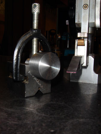
Instead I grabbed a random chunk of scrap from the bin. In the previous setp I laid out a .5" x .5" square on the face of the adapter. While I was still on the lathe I used a .5" end mill in the chuck to cut out the center.
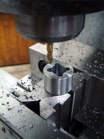
Here I've switched over to the mill and plunged four holes at each corner of the square I scribed. I think it was a 5/16" mill.
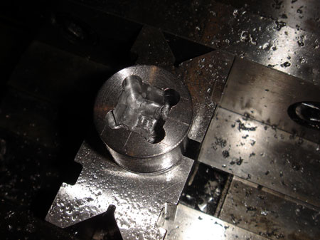
I plunged the corners slightly deeper than the main pocket and then just eyeballed X and Y cuts along the edge untill I had "just" machined away the scribe lines. I was shooting for .51" on all four sides.
To make the flat I just gripped the fat part in the vise and eyeballed the centering and the depth. Worked out fine.
It turns out that the square shaft was a liiiiitle bigger than I had thought. It took about 20 minutes grinding with a dremel tool to get the adapter to fit. A couple of light taps with a plastic mallet seats it nicely with zero slop. Just for good measure I shot some grease in there before I put it on.
Yep it fits. I'm sure real machinists already know this, but a difference of .001 gives a nice sliding fit. Locktite on the setscrew.
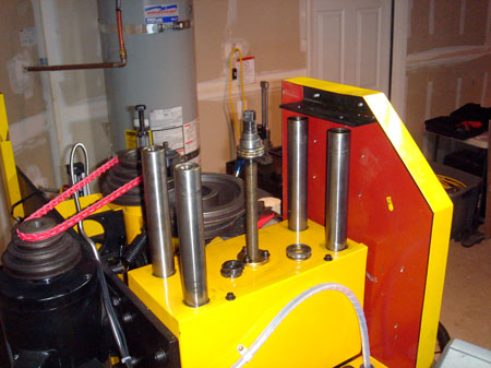
Now I was going to need four holes in the top plate that holds the mill together. I was a bit wary of screwing up the alignment. Throwing caution to the wind I proceeded to remove the plate.
I also made sure to lock down the 5th column support before I removed the plate. Don't know if that's really important but it seemed like it would help keep stress off the lower quadralift mounting bolts.
And yes, that's a Fenner drive belt. I'm just playing with it here but I'm going to be using these when I get my new motors on as well. Comes in handy 25' lengths from MSC.
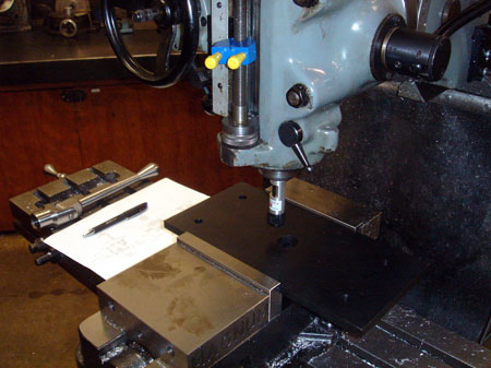
Yep, laser time again. I used it to locate the center of the acme screw hole in about 20 seconds. No layout at all after finding center, just straight to drilling.
I located all four holes by setting setting my part zero at the center of the hole. Then I printed out the manufacturers technical drawing for the motor and used the DRO to move to those four coordinates.
Mounted and looking good. You'll notice the screw is off center from the hole patern because the shaft on the gear motor is off center as well.
One important note here, I moved the column all the way up before I tightened the screws again. Don't know if this matters but the column still rides up and down with no sticking or binding.
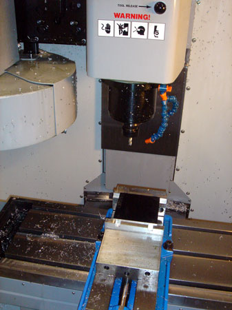
Next up is the actual plate that will mount between my motor and stand-off. Time to put the HAAS Mini Mill through a little workout. Again, I just programed my part zero at the center of the shaft hole and entered coords for the four holes that the all-thread will pass through.
2.1MB avi
Got video? Sorry about the sound, apparently my camera was touching the cabinent and it picked up the vibration...so don't try and "fix" your volume.
The 1" pocket was cut with three incremental Z moves of -.2" with a 3/8" endmill but I haven't shown the whole routine, just the latter part. The rapid travel is at 25% since I was just doing this one part and wanted to have time to hit the stop button...in case.
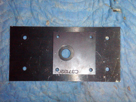
Perfect! I did make the holes 3/8" though I'll be using 1/4-32 all thread. I will need a little slop to make sure the assembly fits up properly, you'll see.
Ah, an exploded view. The big cylinder is another scrap bit. Turns out after machining that and adding in the 1/2" thickness of the adapter plate, the whole thing is EXACTLY the right height to account for the flex coupler and the screw and motor shaft. I mean, I only machined the cylinder ends enough to true them up. Murphy? ah, he left town or something. (knock on wood)
Anyway, time to make the all thread shorter...
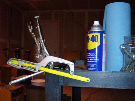
I don't have a bench vise, but I do have a bench and some vise grips.
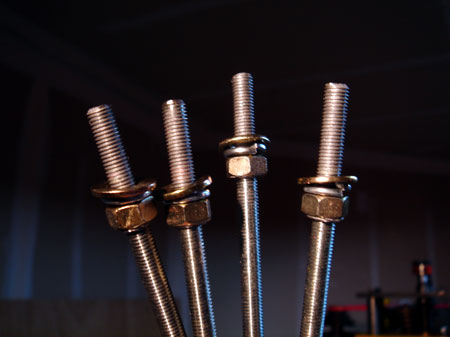
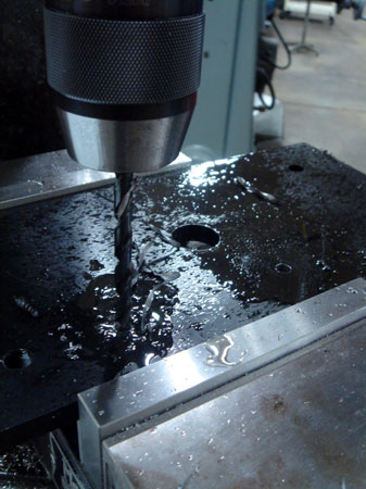
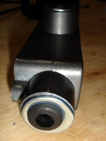
So these ends are going through the adapter plate and into the threaded motor body...like in the very first photo. Can't really see it but I slathered them up with anti-seize grease.
So now you can see the "standoff" and the reason I needed some slop in the mounting holes. I wanted the cylinder to be as centered as possible on the mounting plate, but I didn't want the coupler to rub on the inside.
After fitting up loosely, I pulled the cylinder over till I could feel it hit the coupler, then backed it off about 1/8".
I didn't really plan this but I think it has quite a nice aesthetic as it mirrors the structure of the quadralift itself.
It may not be the best idea to have the coupling enclosed. It was certainly a challenge getting it to line up since I couldn't see it. I considered making a hole in the side. Some people might call this something fancy like an inspection port. Guess I can do that later should I need to "inspect."
Well that's a nice motor, but now your column is stuck right where it is untill you wire in a switch...a reversing switch. Actually a lighted on/off switch and a jog button and a reversing switch. Sounds easy right? Well, I've never really wired anthing before...well anything that didn't come with instructions.
Note: if you are going to do this mod, be SURE to move the quadralift into a "mid" position...especially if you aren't experienced with wiring. You don't want to end up bottoming (or topping) out unexpectedly.
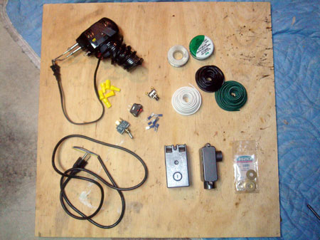
Well, I've never tried to wire up a switch box before. I found some goodies that looked usefull and went after it.
I bought this "reversing" DPDT toggle switch from an Ebay store called "West Florida Components" (no affiliation). They have lots of little electronic widgets.
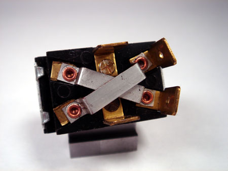
The reversing is accomplished by jumpering the leads that are depicted in the photo. You can accomplish the same effect with any DPDT and a couple of lengths of wire.
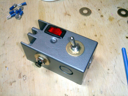
Guess I skipped a couple of steps here. The two round switches are installed via a couple of punch outs. Since the locking collars on the switches are much smaller than the punch out...I took some brass washers and drilled them out with a step drill.
The square switch was installed by milling a hole with a 1/8" endmill. I made a rough paper template, traced around it, and just milled by eyeball and several test fits.
Obviously I also painted this with Rustoleum hammered grey.
I did a bit of recycling here. The power cord I used is the original cord that came with the Shoptasked and was replaced by this cord.
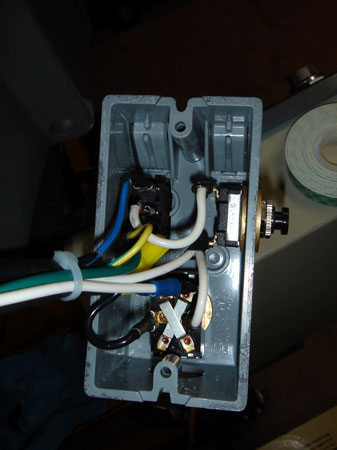
A bit hard to see but the hot line is the blue cord in the top left. The lighted switch needs it's third spade grounded to work. Next I ran the line through my jog switch and then split it with one lead running to the common on the reverse toggle and the other line to the motor.
I know I'm using the wrong color wire. It wasn't exactly self explanitory when I started out so I had to try a couple different things before I got it right. By then I had cut and soldered a lot of wire and didn't want to waste it. Anyway, it works now and that's good enough for me.
I was ultimately thinking I wanted to wire these controls to my AB box as well, but I really like the one eyed robot head thing I have going here.
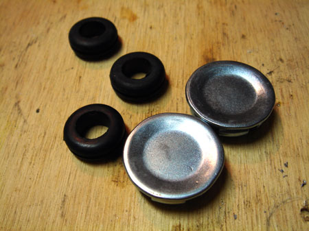
Some grommets and electrical caps.
I can't remember what this is called in electrical terms but I'll call it a box. I didn't want my wire running into big holes where chips would get trapped so this was my solution. I love step drills.
Ah there we go. It really went MUCH easier after I downloaded the correct wiring diagram from Bodine Electric. Initially I was getting "down" motion but I couldn't switch it to the "up" direction...silly reversing switch.
This is the reason I mentioned earlier that you should leave the column in the middle of it's travel. Very handy in case you have any wiring issues to trouble shoot. It would have been a bummer if I had bottomed out before solving the problem.
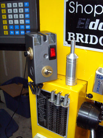
Anyway, right now the box just dangles, I'm not sure where to mount it.
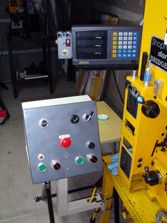
I did; however, find the perfect place to mount my robot-head-pendant. You can see the double sided foam tape on the little table in the background. I know the stuff as "servo" tape and it works wonders.